form and practicality
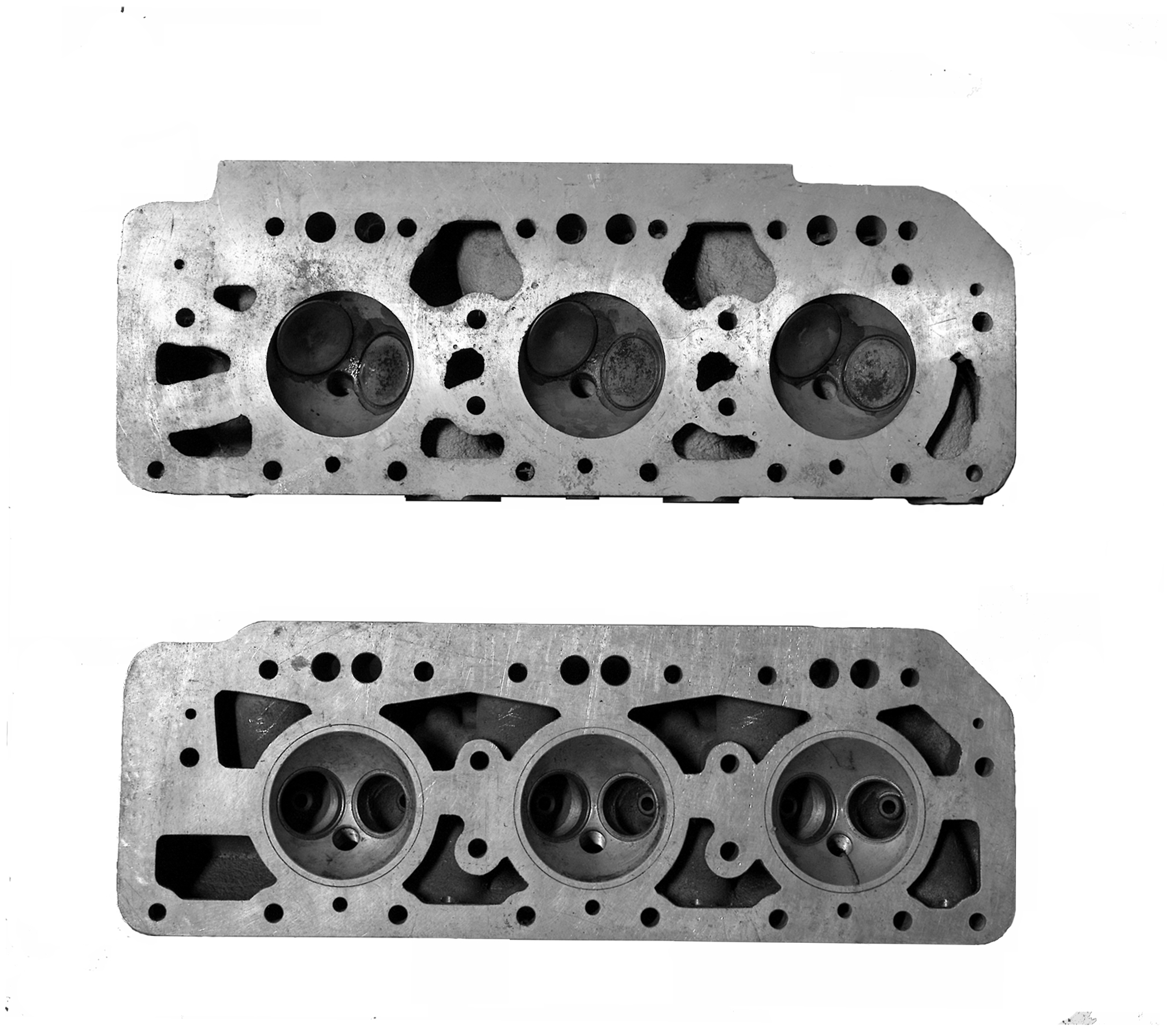
two heads – B20 s.1 and s.4
Over the life of the Aurelia there were many changes to the car. In fact, from the s. 1 to s. 6 B20, it is hard to find components that were not changed, mostly small bits here and there as all the major parts were revised. Some of these changes were due to learning more about what was needed for a part to work. This can be seen in a comparison of the engine heads from a s.1 B20 from 1951 with a s.4 B20 of 1954/55.
The most striking difference is in the water passages – in the earlier head, they are precisely shaped, as drawn by an engineer, and carefully and formally arranged. Quite nicely so. A few years later, a different picture emerges – the passages in the s.4 head are located slightly differently, and shaped practically. Probably easier to cast, and likely more effective.
Its a small item, buried away inside the engine and no one will ever see it. But its one of the many changes that tell of the dialogue at that time between Lancia’s engineers and their production. Its a dialogue that goes on today, still. Form and practical – two ideas that need each other, as neither does well without the other.
Interesting. But I wonder if it may not be a case of the S1 head being optimized for flow speed, and the S4 head being optimized for volume. The S4 passages certainly are more “generic” in shape, but there’s more contact area with the cylinders and a narrower separation; it looks like it has better transfer. That said, it might be down to production decisions, and the performance difference was simply a side benefit.
Ed Levin
May 26, 2013 at 5:49 am
From John Cundy, an English engineer and B20 owner, and friend:
“The probable reason for changing the cooling flow holes in the later head is to improve the cooling! This is dominated by the exhaust valve seat, guide and port. The early head looks as though it was “drawn”. The later has been “developed”, probably because the extra power was showing up problems. They would probably have run with thermocouples at a number of chosen positions then played around with the hole areas to get all exhausts to a similar temperature and as cool as possible. The two smaller holes at top centre and deletion of those at the top corners will bias the flow to the exhausts. They would also be mindful of the strength of the deck and the load paths from the head studs into the deck where the later head looks a bit better.”
Geoff
May 28, 2013 at 4:01 am